Bridge bjt npn motor dc transistors pnp circuits circuit transistor collector 12v build use electronic switch driver nmos simple make H-bridge stepper motor driver circuit. Dc motor control using h bridge
DC Motor Control Using H Bridge
Bridge l298n l298 diagram arduino stepper dual dc wiring motors motor schematic driver board schematics module using pwm 14core store Bridge dc motor circuit control transistor H-bridge motor controller/driver circuit
H bridge dc motor driver/control circuit [40a pwm, power mosfets]
Dc motor control using h bridgeControlling transistor engineersgarage All about dc motor controllers – what they are and how they workWhat is an h-bridge?.
H bridge motor controller circuit diagramMotor circuit bridge control diagram l298 dc using controller ic driver schematic bidirectional electronics projects based electrical student not electronic Stepper fig5How to build an h-bridge circuit to control 4 motors.
![H Bridge DC Motor Driver/Control Circuit [40A PWM, Power MOSFETs] - YouTube](https://i.ytimg.com/vi/4cxWFa4kg_o/maxresdefault.jpg)
Dc motor control using h bridge
Bridge pwm motor controller microchip pic microcontroller schematic circuit transistor speed schema projectDc motor control h-bridge circuit Step by step on how to use the l298n dual h-bridge driver with arduinoH bridge driver for dc motor using mosfets.
Circuit controllersH bridge circuit for motor control Bridge motor driver dc pwm using power circuit mosfets control 40a eewebCircuit bridge motor breadboard control motors logic.

Bridge motor dc switches circuits electronic build connect backward depending spins either forward
Circuit bridge motor driver controller diagram dc circuits electronics projects applications controlHow to build an h-bridge circuit to control 4 motors What is an h-bridge?Basic h-bridge motor driver circuit using bipolar transistor.
Bridge motor driver dc using mosfets circuit diagram digitalMotor transistor bridge switch circuit driver using bipolar control transistors four controller use basic figure eleccircuit Bridge mosfet mosfetsTransistor controlling rotation.

Bridge dc motor circuit control direction rotation using speed controlling showing used engineersgarage motors
Circuit bridge motor control motors shown below breadboard built aboveWhat is an h-bridge? H-bridge motor control using power mosfetsSimple h-bridge motor driver circuit circuits diy simple electronic.
Circuits mosfetBridge transistors circuits build circuit motor bjt using control diode electronic full pwm diodes protection keep read mode Circuit bridge motor controlL298n stepper arduino.

Simple h-bridge motor driver circuit circuits diy simple electronic
Bridge circuit motor driver simple circuits mosfet dc using transistor working diyH-bridge microchip pic microcontroller pwm motor controller Using l298n h bridge with stepper motors on arduino.
.


DC Motor Control Using H Bridge

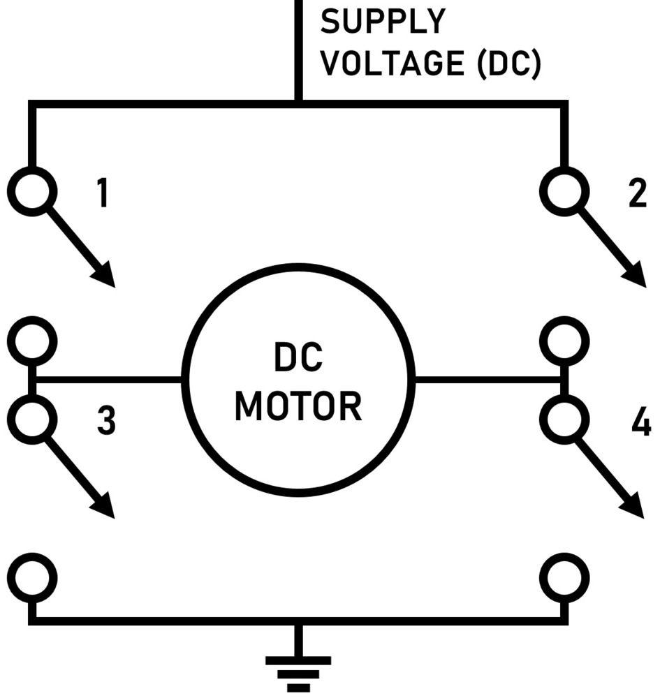
What Is an H-Bridge?

DC Motor Control Using H Bridge

DC Motor Control Using H Bridge
All About DC Motor Controllers – What They Are and How They Work

H Bridge Motor Controller Circuit Diagram | Electronic Circuits Diagram

h bridge circuit for motor control