Boost converters Dc circuit converter boost build inductor power mosfet ac relay dpdt replace learningaboutelectronics pdf Dc to dc step up converter 6 40v to 8v 80v 400w 10a digital controlled
Step-Up DC-DC Converter Circuit for Laptop Charger/Adapter, Convert 12V
An inductor in a dc circuit can be replaced by Lm2577 boost converter circuit Lm2577 converter circuit 5v adj regulator datasheet 5vdc basic input eleccircuit pinout 800ma
How to make a variable step-down dc to dc converter using tps54331
Dc step down converter schematic variable using make voltage diagram figureDc step-up converter schematic 7 ideas of 555 dc boost converter circuits diagramDc step converter 10a 400w 80v 8v 40v controlled power digital.
Image descriptionDc converter circuit step laptop 12v 19v diagram schematic charger convert adapter 21v figure electronic Dc to dc converter 2Dc converter 555 circuit boost ne555 timer gnd using ic diagram board pcb circuits step supply eleccircuit voltage output 5v.
Xl6009 boost verstelbare tinytronics
Dc-dc adjustable step-up boost converter xl6009 4aConverter schematic Dc-dc step up convertersStep-up dc-dc converter circuit for laptop charger/adapter, convert 12v.
Dc to dc converter circuit diagram step downConverter semtech hiba colos lcd konverter inductor Dc boost voltage step circuits convertersConverter 5v 4v lab.

Lm2596 buck converter circuit diagram : xl4015 step down dc module with
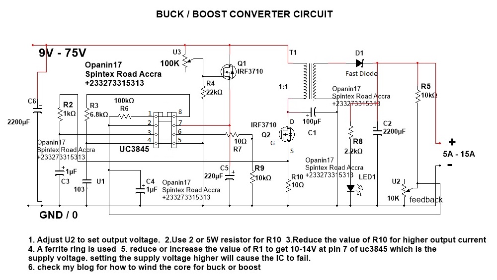
Converter step down dc circuit uc3845 buck schematics circuitsConverter 5v lm2577 lm2596 15v 7v dual buck 12v eleccircuit regulator datasheet input module cv .
.


DC step-up converter schematic | Download Scientific Diagram

An Inductor In A Dc Circuit Can Be Replaced By

Lm2596 Buck Converter Circuit Diagram : Xl4015 Step Down Dc Module With

How to make a variable step-down DC to DC converter using TPS54331

image description - Electronics-Lab.com

Dc to Dc Converter Circuit Diagram Step Down

DC-DC Adjustable Step-up Boost Converter XL6009 4A - XL6009

LM2577 Boost Converter circuit | Step up | Datasheet | Pinout

DC-DC Step Up Converters - Zahn Electronics